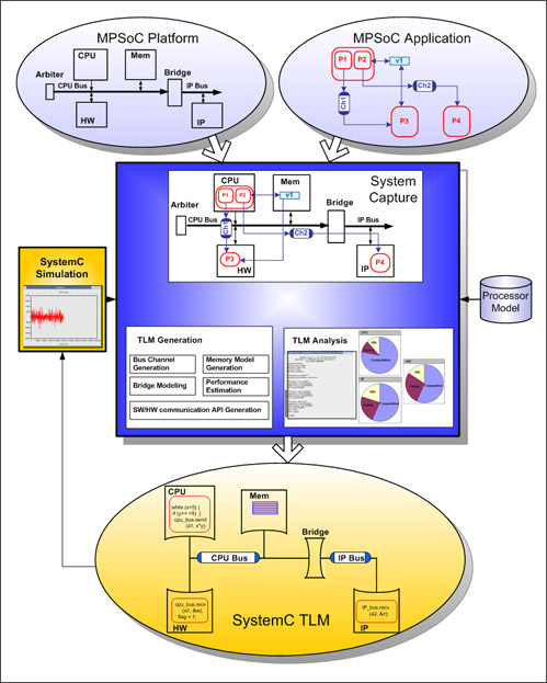
最近花了點時間研究 LLVM 跟後端的 Hardware Synthesis flow. 感覺有滿多東西可以做的. 如 pipeline DFG, parallel DFG, memory partition, bus interface... 底下就先用"最最最"簡單的例子來講解一下如何透過 LLVM 當前端的 Input ,跟後端的 Hardware Synthesis 是如何結合的.
Step1. LLVM environment set
假設 LLVM 的環境都已經 ready. 沒有 ready 可以參考
LLVM 2.8 env set && pass manager set
step2. sample hardware code @ c
一個
Image scaling 最常用到的 Hardware sample IP. 就 o_c = (in_a + in_b)>>1;而 (*) pointer 表示從外部的 memory load/store 進來到loacl 的 IP.
//
//#include <iostream>
//
//using namespace std;
//
void test(int *i_a,int *i_b, int *o_c){
 *o_c = (*i_a+*i_b)>>1;
}
//int main(){
//int a=1, b=1;
//int c;
// test(&a,&b,&c);
// cout
step3. compile && LLVM IR gen
利用 clnag compile 出 LLVM 的 byte code, 之後再轉成有點像 machine code 的ll format.
% clang -O3 -emit-llvm test.c -c -o test.bc
% llvm-dis test.bc
在 test.ll 中,可以發現 load/store 的 instructions. 跟我們之前的假設相同.
IR format 就請參考
LLVM Language Reference Manual
define void @test(i32* nocapture %i_a, i32* nocapture %i_b, i32* nocapture %o_c) nounwind {
entry:
  %tmp1 = load i32* %i_a, align 4, !tbaa !0
  %tmp3 = load i32* %i_b, align 4, !tbaa !0
  %add = add nsw i32 %tmp3, %tmp1
  %shr = ashr i32 %add, 1
  store i32 %shr, i32* %o_c, align 4, !tbaa !0
  ret void
}
step4. LLVM IR Get && sample Graph Gen
利用 share lib 的方式依序取的 instruction type 跟 Data.建立起我們後端的sample Graph.
ps: Graph 中可以定義每個 instruction 的 Delay 跟 hardware resource constrain ..., 再透過 Schedule Algorithm 來決定每個 Node 所在的 Cycle.

假設無 hardware, Memory constrain , Run Schedule Algorithm 後得到以下的結果.分別表示 Memory load 需要 2 個 clock cycle, Memory Store 需要 3 個 clock cycle, 而 Internal IP 只需要 1 個 clock cycle 就可完成.

假設只有一個 Memory 的情況下,變成要分成兩次 memory Load.導致total 的 cycle time 增加.

resource sharing. 減少 Hardware cost.

如果是 for loop 的 case 也可以猜成 pipeline 的型態.

ps: 應該過不久就可以把sample 寫好放上來跟大家一起研究研究摟.
Loop optimization
Ref: CFG definition
http://en.wikipedia.org/wiki/Control_flow_graph
Analysis and Representation of Loops
Trident: From High-Level Language to Hardware Circuitry - LLVM
 假設無 hardware, Memory constrain , Run Schedule Algorithm 後得到以下的結果.分別表示 Memory load 需要 2 個 clock cycle, Memory Store 需要 3 個 clock cycle, 而 Internal IP 只需要 1 個 clock cycle 就可完成.
 假設只有一個 Memory 的情況下,變成要分成兩次 memory Load.導致total 的 cycle time 增加.
 resource sharing. 減少 Hardware cost.
 如果是 for loop 的 case 也可以猜成 pipeline 的型態.
 ps: 應該過不久就可以把sample 寫好放上來跟大家一起研究研究摟.
Loop optimization
Ref: CFG definition
http://en.wikipedia.org/wiki/Control_flow_graph
Analysis and Representation of Loops
Trident: From High-Level Language to Hardware Circuitry - LLVM


